Plant Description
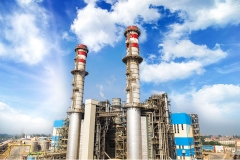
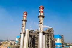
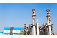
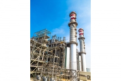
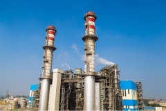
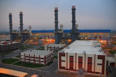
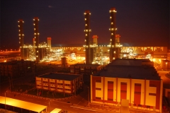
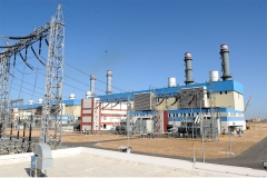
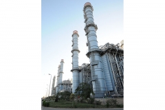
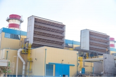
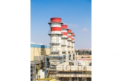
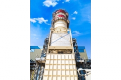
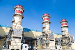
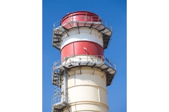
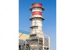
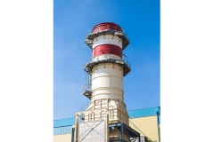
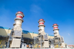
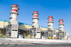
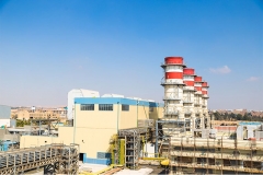
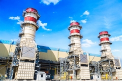
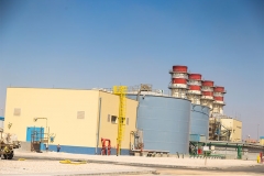
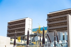
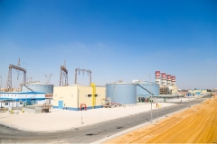
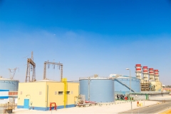
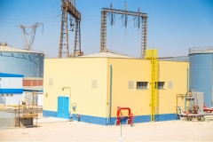
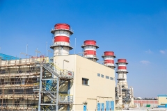
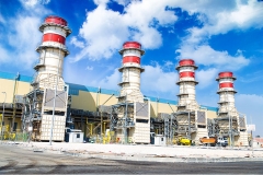
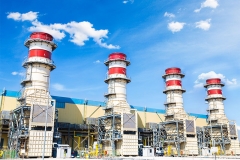
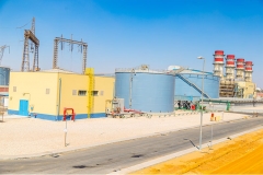
The West Damietta site is located on the Mediterranean Sea north coast, 15 km west of the New Damietta port near Damietta City. The existing facility consists of four (4) outdoor combustion turbine generators (CTGs) GE Frame 9E (4 x 125 MW) installed and commissioned in 2011. The new project accommodates one combined cycle module. It has a 4x4x1 configuration consisting of four (4) combustion turbines from the existing units. Each one feeds its exhaust gases to its respective heat recovery steam generator (HRSG), for a total of four (4) HRSGs and one 250 MW nominal steam turbine unit. Steam generated from the four (4) HRSGs feeds one 250 MW, non-reheat, condensing steam turbine generator (STG).
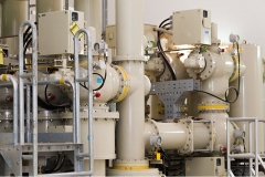
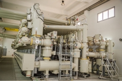
The new facility estimated 250 MW net output is achieved by burning natural gas in the CTGs with no supplementary firing in the HRSGs. The steam exhausted from the steam turbine is discharged into air cooled condenser. Air is used for the power plant cooling demand. Power generated is stepped up through a main transformer and fed to the utility grid via an onsite GIS existing switchyard facility 220 kV over head transmission line (OHTL). The current switchyard has space for one spare bay adequate for the new steam turbine unit.
The project contracting plan utilized a multi-package system. Eight (8) contracting packages and purchase orders procured the equipment and services.
Plant Description
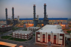
Al Shabab site is located 33 Km West and 10 km South of Ismailia and El-Kassassin Cities respectively, in the Ismailia Governorate. The existing facility consists of eight (8) outdoor combustion turbine generators (CTGs) GE Frame 9E (8 x 125 MW) installed and commissioned in 2011.
The new project accommodates two (2) combined cycle modules. Both modules have a 4x4x1 configuration consisting of four (4) combustion turbines from the existing units. Each one feeds its exhaust gases to its respective heat recovery steam generator (HRSG) for a total of four (4) HRSGs and one 250 MW nominal steam turbine unit. Steam generated from the four (4) HRSGs feeds one 250 MW, non- reheat, condensing steam turbine generator (STG).
The new facility estimated 500 MW net output is achieved when burning natural gas in the CTGs with no supplementary firing in the HRSGs. The steam exhausted from the steam turbine is discharged into an air cooled condenser. Air is used for the power plant cooling demand. Power generated is stepped up through main transformers and fed to the utility grid via an onsite GIS existing switchyard facility 220 kV over head transmission line (OHTL). The current switchyard has space for two spare bays adequate for the new steam turbine units.
The project contracting plan utilized a multi-package system. Eight (8) contracting packages and purchase orders procured the equipment and services.
Plant Description
Banha power project includes a power block that consists of two 250 MW Combustion Turbine Generators (CTGs). Each one feeds exhaust gases to its respective unfired Heat Recovery Steam Generator (HRSG). Steam from the two HRSGs feeds one 250 MW, single reheat, condensing Steam Turbine Generator (STG).
The estimated 750 MW net output is achieved by burning natural gas in the CTGs without supplementary HRSG firing. Nitrogen oxides of nitrogen (NOx) emissions are controlled by dry low-NOx (DLN) combustors. An inlet air filtration system supplies filtered combustion air to the CTGs. The steam exhausted from the steam turbine feeds a once-through cooling, single-pass, divided water box condenser.
Power is generated at manufacturer standard voltage in the CTGs and the STG, stepped up through main transformers, and fed to the grid via a 220 kV, GIS switchyard. The Rayah Tawfiki provides the plant cooling water.
The project contracting plan utilized a multi-package system. Sixteen (16) contracting packages and purchase orders procured the equipment and services.
Plant Description
Giza North power project consists of three modules each module includes two 250 MW Combustion Turbine Generators (CTGs). Each one feeds exhaust gases to its respective unfired Heat Recovery Steam Generator (HRSG). Steam from the two HRSGs feeds one 250 MW, single reheat, condensing Steam Turbine Generator (STG).
The estimated 2250 MW output is achieved by burning natural gas in the combustion turbines with no supplementary HRSG firing. Nitrogen Oxide (NOx) emissions are controlled by dry low-NOx (DLN) combustors. An inlet air filtration system is included to supply suitably filtered combustion air to the CTGs. The steam exhausted from the steam turbine is feeds a once-through cooling, single-pass, divided water box condenser.
Power is generated at manufacturer standard voltage in the CTGs and the STG, stepped up through main transformers, and fed to the National grid via a 500 kV & 220 kV, GIS switchyard. The Rayah Behery provides the plant cooling water.
The project contracting plan utilized a multi-package system. Seventeen (17) contracting packages and purchase orders procured the equipment and services.
Plant Description
El Atf power project consists of two 250 MW combustion turbine generators (CTGs). Each one feeds ex-haust gases to its respective unfired heat recovery steam generator (HRSG) with no supplementary firing. Steam from two HRSGs feeds one 250 MW, single reheat, condensing Steam Turbine Generator (STG).
The estimated 750 MW net output is achieved by burning natural gas in the CTGs without supplementary HRSG firing. Nitrogen Oxide (NOx) emissions are controlled by dry low-NOx (DLN) combustors. An inlet air filtration system supplies filtered combustion air to the CTGs. The steam exhausted from the steam turbine feeds a once-through cooling, single-pass, divided water-box condenser.
Power is generated at manufacturer standard voltage in the CTGs and the STG, stepped up through main transformers, and fed to the National grid via a 220 kV, GIS switchyard. The Nile River provides the plant cooling water which is then discharged to the Marquase Canal.
The project contracting plan utilized a multi-package system. Sixteen contracting packages and purchase orders procured the equipment and services.
Plant Description
Sidi Krir power project consists of two 250 MW combustion turbine generators (CTGs). Each one feeds exhaust gases to its respective unfired heat recovery steam generator (HRSG). Steam from the two HRSGs is fed to one 250 MW, single reheat, condensing Steam Turbine Generator (STG).
The estimated 750 MW net output is achieved when burning natural gas in the combustion turbines without supplementary HRSG firing. Nitrogen Oxides (NOx) emissions are controlled by dry low-NOx (DLN) combustors. An inlet air filtration system supplies filtered combustion air to the CTGs. The steam exhausted from the steam turbine feeds a once-through cooling, single-pass, divided water box condenser.
Power is generated at manufacturer standard voltage in the CTGs and the STG, stepped up through main transformers, and fed to the National grid via a 500 kV, GIS switchyard. The Mediterranean Sea provides the plant cooling water.
The project contracting plan utilized a multi-package system. Sixteen (16) contracting packages and purchase orders procured the equipment and services.
Plant Description
Kureimat III power project includes a power block that consists of two 250 MW combustion turbine generators (CTGs). Each one feeds exhaust gases to its respective heat recovery steam generator (HRSG). Steam from two HRSGs feeds one 250 MW (nominal), reheat, condensing steam turbine generator (STG).
The estimated 750 MW net output is achieved by burning natural gas in the CTGs without supplementary HRSG firing. Nitrogen Oxide emissions are controlled by dry low-NOx (DLN) combustors. An inlet air filtration system supplies filtered combustion air to the CTGs. The steam exhausted from the steam turbine feeds into a once-through cooling, single-pass, divided water-box condenser.
Power is generated at manufacturer standard voltage in the CTGs and the STG, stepped-up through main transformers and fed to the utility grid via the extension of the existing 220 kV, gas-insulated switchgear (GIS) switchyard. The Nile River provides the plant cooling water.
The project contracting plan utilized a multi-package system. Five (5) contracting packages and purchase orders procured the equipment and services.
Plant Description
Kureimat II power project includes a power block that consists of two 250 MW combustion turbine generators (CTGs). Each one feeds exhaust gases to its respective heat recovery steam generator (HRSG). Steam from the two HRSGs feeds one 250 MW (nominal), reheat, condensing steam turbine generator (STG).
The estimated 750 MW net output is achieved by burning natural gas in the CTGs without supplementary HRSG firing. Nitrogen Oxide (NOx) emissions are controlled by dry low-NOx (DLN) combustors. An inlet air filtration system is included to supply suitably filtered combustion air to the CTGs. The steam exhausted from the steam turbine feeds a once-through cooling, single-pass, divided water box condenser.
Power is generated at 21 kV (or manufacturer standard voltage) in the CTGs and the STG, stepped up through main transformers, and fed to the utility grid via the existing a new 220 kV (GIS) switchyard. The Nile River provides the plant cooling water.
The project contracting plan utilized a multi-package system. Eight (8) contracting packages and purchase orders procured the equipment and services.
Plant Description
Talkha power project consists of two 250 MW combustion turbine generators (CTGs). Each one feeds exhaust gases to its respective unfired heat recovery steam generator (HRSG). Steam from the two HRSGs feeds one 250 MW, reheat, condensing steam turbine generator (STG).
The estimated 750 MW net output is achieved by burning natural gas in the CTGs with no supplementary firing in the HRSGs. Nitrogen oxide (NOx) emissions are controlled by dry low-NOx (DLN) combustors. An inlet air filtration system is included to supply suitably filtered combustion air to the CTGs. The steam exhausted from the steam turbine feeds a once-through cooling, single-pass, divided water box condenser.
Power is generated at 21 kV (or manufacturer standard voltage) in the CTGs and the STG, stepped up through main transformers, and fed to the utility grid via the existing 220 kV (GIS) switchyard. The Damietta branch of the Nile River provides the plant cooling water.
The project contracting plan utilized a multi-package system. Eight (8) contracting packages and purchase orders procured the equipment and services.
Plant Description
Nubaria III power project consists of one module 750 MW comprised of two 250 MW combustion turbine generators (CTGs). Each one feeds exhaust gases to its respective heat recovery steam generator (HRSG) with no supplementary firing. Steam from the two HRSGs is fed to one 250 MW, reheat, condensing steam turbine generator (STG). Nitrogen Oxide emissions are controlled by dry low NOx (DLN) combustors. An inlet air filtration system supplies filtered combustion air to the CTGs. The steam exhausted through the steam turbine feeds a once-through cooling, single-pass, divided water-box condenser.
Power is generated at manufacturer standard voltage in the CTGs and the STG, stepped-up through main transformers and fed to the national grid via a 500 kV, conventional switchyard. The Rayah El Nasery Canal provides the plant cooling water.
The project contracting plan utilized a multi-package system. Fourteen (14) contracting packages and purchase orders procured the equipment and services.
Plant Description
Nubaria I&II power project is two slides along modules delivering 1500 MW (750 MW each). Both modules include two 250 MW combustion turbine generators (CTGs). Each one feeds exhaust gases to its respective heat recovery steam generator (HRSG) with no supplementary firing. Steam from the two HRSGs feeds one 250 MW, reheat, condensing steam turbine generator (STG). Nitrogen Oxide (NOx) emissions are controlled by dry low-NOx (DLN) combustors. An inlet air filtration system supplies filtered combustion air to the CTGs. The steam exhausted from the steam turbine feeds a once-through cooling, single-pass, divided water box condenser.
Power is generated at manufacturer standard voltage in the CTGs and the STG, stepped up through main transformers, and fed to the national grid via a 500 kV and a 220 kV, conventional switchyard. The Nubaria Canal provides the plant cooling water.
The contracting plan utilized a multi-package system. Twenty-two (22) contracting packages and purchase orders procured the equipment and services.
Plant Description
Cairo North power project consists of two modules each module includes two 250 MW combustion turbine generators (CTGs). Each one feeds exhaust gases to its respective heat recovery steam generator (HRSG). Steam from two HRSGs feeds one 250 MW, reheat, condensing steam turbine generator (STG).
The estimated 1500 MW net output is achieved by burning natural gas in the CTGs without supplementary HRSG firing. Nitrogen Oxide (NOx) emissions are controlled by dry low-NOx (DLN) combustors. An inlet air filtration system supplies filtered combustion air to the CTGs. The steam exhausted from the steam turbine feeds a once-through cooling, single-pass, divided water box condenser.
Power is generated at 21 kV (or manufacturer standard voltage) in the CTGs and the STG, stepped up through main transformers, and fed to the utility grid via a 220 kV (GIS) switchyard. The Ismailia Canal provides the plant cooling water.
The project contracting plan utilized a multi-package system. Sixteen (16) contracting packages and purchase orders procured the equipment and services.
The 6 of October II Extension power project is a simple cycle power generation project located beside the Extra High Voltage Researches Lab fence area, 25 km from Cairo on the Cairo –Alexandria desert road. It consists of four indoor gas turbines with a total capacity of 640 MW. The facility includes all necessary auxiliary equipment including a new natural gas reducing and handling facility. Power generated at the manufacturer standard voltage for the CTG is stepped up through main transformers and fed to the utility unified grid via a 220 kV Gas Insulated Switchyard (GIS). The project was executed through a lump sum turnkey contract.
The project utilized an EPC contracting plan. As the Owner authorized representative, PGESCo was responsible for the overall project management, design review, and construction management as well as startup and commissioning management.
The 6 of October I power project is simple cycle power generation project located inside the Extra High Voltage Researches Lab fence area, 25 km from Cairo on the Cairo –Alexandria desert road.
The project consists of four indoor gas turbines with a total capacity of 600 MW. The facility includes all necessary auxiliary equipment including a new natural gas reducing and handling facility and water treatment facilities.
Power generated at the manufacturer standard voltage for the CTG is stepped up through main transformers and fed to the utility unified grid via an onsite 220 kV Gas Insulated Switchyard (GIS). The project was executed through a lump sum turnkey contract. The project utilized an EPC contracting plan.
West Damietta power project is a simple cycle power generation project located within the vicinity of the existing West Damietta power station. It consists of four outdoor gas turbines with a total capacity of 500 MW. The facility includes all necessary auxiliary equipment including a new natural gas reducing and handling facility and wastewater treatment facilities. Power generated at the manufacturer standard voltage for the CTG is stepped up through main transformers and fed to the utility unified grid via an onsite 220 kV Gas Insulated Switchyard (GIS). The project was executed through a lump sum turnkey contract.
Damietta power project is a simple cycle power generation project located near the vicinity of the existing Damietta power station. It consists of four outdoor gas turbines with a total capacity of 500 MW.
The facility includes all necessary auxiliary equipment including a new natural gas reducing and handling facility and wastewater treatment facilities.
Power generated at the manufacturer standard voltage for the CTG is stepped up through main transformers and fed to the utility unified grid via an onsite 220 kV Gas Insulated Switchyard (GIS). The project was executed through a lump sum turnkey contract.
The project utilized an EPC contracting plan.
Al Shabab power project is a simple cycle power generation project located near the vicinity of the existing Al Shabab power station.
It consists of eight outdoor gas turbines with a total capacity of 1000 MW.
The facility includes all necessary auxiliary equipment including a new natural gas reducing and handling facility and wastewater treatment facilities.
Power generated at the manufacturer standard voltage for the CTG is stepped up through main transformers and fed to the utility unified grid via an onsite 220 kV Gas Insulated Switchyard (GIS). The project was executed through a lump sum turnkey contract.
The project utilized an EPC contracting plan.
Plant Description
Suez power projects is designed to include a 1 x 650 MW steam thermal power plant to interconnect with the National Unified Power System (NUPS) through a 220 KV GIS switchyard. The power block is comprised of one Rankine cycle turbine generator unit with a nominal rated capacity of 650 MW. The unit is capable of generating rated capacity using natural gas, residual (mazout) oil, or a combination of both. The unit station arrangement includes an enclosed turbine building, an open boiler building, a control room, and all associated structures and facilities.
The project contracting plan utilized a multi-package system. Nineteen (19) contracting packages and purchase orders procured the equipment and services.
